Editing Paths and Autos
Paths
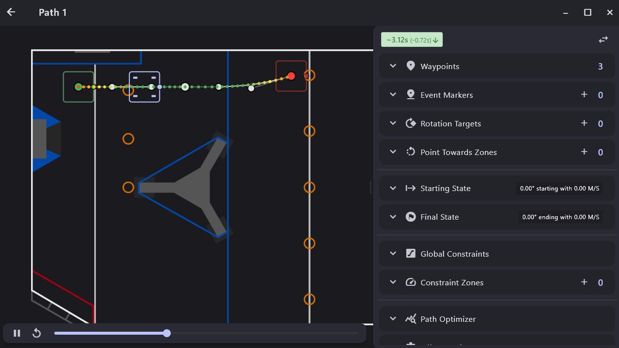
In PathPlanner, paths are used to create one continuous motion from some start point to an end point. In other words, each path describes a singular segment of an autonomous routine. For instance, driving from the start point to pick up a game piece, driving from the game piece to a scoring position, and driving from the scoring position to an end position are all separate paths. Paths defined this way can be chained together and reused in the modular auto system.
Waypoints
Within paths, waypoints are the positions on the field the define the shape of the spline that the robot will follow. Each waypoint consists of two types of points: anchor points and control points. Anchor points define the exact position that the spline will pass through, and control points are used to define the heading, or tangent, of the spline as well as to fine-tune the shape of the spline via the control point's distance from its associated anchor point.
Waypoints can be added to a path by double-clicking on the field within the path preview. A new waypoint will be added to the end of the path at the clicked location. Waypoints can be edited by click and drag in the path preview, or via the waypoints tree.
Waypoints Tree
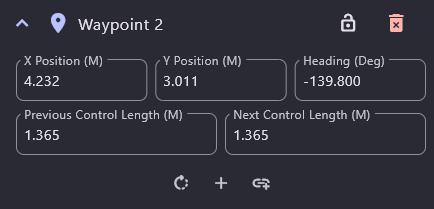
- Lock Button
Locks the waypoint to prevent it from being changed by dragging it around in the path preview. This will still allow the control point lengths to be changed via click and drag.
- Delete Button
Delete the waypoint from the path
- X Position
X Position of the waypoint's anchor point on the field in meters.
- Y Position
Y Position of the waypoint's anchor point on the field in meters.
- Heading
The heading, or direction of travel, of the robot while passing through this point in degrees.
- Previous Control Length
The distance between the anchor point and the previous control point in meters.
- Next Control Length
The distance between the anchor point and the next control point in meters.
- Add Rotation Target Button
Adds a new rotation target to the path at the position of the selected waypoint.
- New Waypoint After Button
Inserts a new waypoint in the path after the selected waypoint.
- Link Waypoint Button
Link this waypoint to other waypoints by giving them a shared name. Updating the position of one linked waypoint will update the positions of all other waypoints linked to it in all other paths.
Global Constraints
Global Constraints define the kinematic constraints of the robot along the entire path. These constraints will be used anywhere that is not covered by a constraints zone. The global constraints can be edited via the Global Constraints tree.
Global Constraints Tree
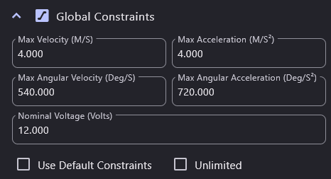
- Max Velocity
The maximum velocity of the robot in meters/sec.
- Max Acceleration
The maximum acceleration of the robot in meters/sec^2.
- Max Angular Velocity
The maximum angular velocity of the robot in degrees/sec.
- Max Angular Acceleration
The maximum angular acceleration of the robot in degrees/sec^2.
- Nominal Voltage
The nominal battery voltage during the path in volts. This is effectively a max velocity and max angular velocity constraint that can be used to properly limit those speeds when you expect the battery voltage to sag during auto due to other systems running such as a shooter or intake. This constraint is still used for unlimited constraints.
- Use Default Constraints
Ties these constraints to the default constraints in the settings menu.
- Unlimited
Use unlimited constraints for this path. If unlimited, the robot will move as fast as the torque output will allow.
Ideal Starting State
The ideal starting state defines the state the robot should be at when starting the path. This will be used to pre-generate the trajectory which will be followed if the robot matches this state when it starts to follow this path. This can be edited via the goal end state tree, or the rotation (holonomic mode only) can be edited via click and drag in the path preview.
Ideal Starting State Tree

- Velocity
The velocity that the robot should start the path with, in meters/sec. Non-zero velocities means that the robot will not be stationary at the start point.
- Rotation
The goal rotation for the robot at the start of the path, in degrees. Only available when holonomic mode is on.
Goal End State
The goal end state defines the target state of the robot when the path ends. This can be edited via the goal end state tree, or the rotation (holonomic mode only) can be edited via click and drag in the path preview.
Goal End State Tree

- Velocity
The velocity that the robot should end the path with, in meters/sec. Non-zero velocities means that the robot will not stop at the end point.
- Rotation
The goal rotation for the robot at the end of the path, in degrees. Only available when holonomic mode is on.
Rotation Targets
Rotation targets define points along the path where the robot should target a given rotation. When path following, the robot will look ahead for the next rotation target, then attempt to rotate to its associated rotation. Rotation targets can be edited in the rotation targets tree. This is only available when holonomic mode is on.
Rotation Targets Tree
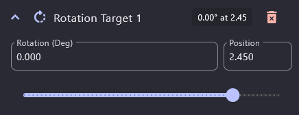
- Rotation
The rotation that should be targeted, in degrees.
- Position Slider
Controls the rotation target's waypoint relative position along the path.
Event Markers
Event markers define points along the path where other commands should be triggered while path following. Each event marker has a command group associated with it that can be used to build more complex functionality via adding named commands, wait commands, and nested command groups. Please note that when the robot reaches the end of a path, all commands triggered via event markers are commanded to end. If you'd like a command to activate when the robot reaches the end of a path, you may want to either experiment with Autos, or place that command at the start of the next path.
Event markers also have the option to be used as triggers, which allow for binding commands to the start/end of an event zone, combine multiple triggers together, using other conditions, etc.
Event Markers Tree
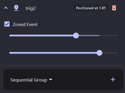
- Zoned Event Checkbox
Indicates whether this event marker should be zoned. Zoned events will have a start and end position that controls when their associated command gets scheduled/canceled, and when their associated trigger goes true/false. If an event is not zoned, its command will not be canceled unless it is still running at the end of a path, while its trigger will go true for one loop.
- Start Position Slider
Controls the event marker's starting waypoint relative position along the path.
- End Position Slider
Controls the event marker's ending waypoint relative position along the path. Only available for zoned events.
- Command Tree
Defines the command that will be run when reaching the event marker.
Constraint Zones
Constraint zones are used to change the kinematic constraints of the robot for a given region of the path. This allows for fine control over the maximum velocity and acceleration of the robot throughout the entire path. Multiple constraint zones can be added to the path and they can overlap. At a given point along the path, the constraints for the zone closest to the top of the list of zones will be used. If there is no constraint zone, the global constraints will be used. Constraint zones can be edited via the constraint zones tree.
Constraint Zones Tree
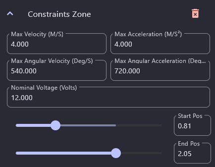
- Constraints
Identical configuration as global constraints. Minus the ability to use defaults or unlimited constraints.
- Start Position Slider
Controls the waypoint relative position of the start of the zone.
- End Position Slider
Controls the waypoint relative position of the end of the zone.
Point Towards Zones
"Point Towards" Zones are used to create a zone along a path where the robot should aim at a position on the field.
Point Towards Zones Tree
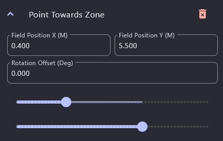
- Field Position X
The X coordinate of the target field position, in meters.
- Field Position Y
The Y coordinate of the target field position, in meters.
- Rotation Offset
An additional rotation to add to the angle to target when in the zone, in degrees. Can be used to have the robot point away from the target position, for example.
- Start Position Slider
Controls the waypoint relative position of the start of the zone.
- End Position Slider
Controls the waypoint relative position of the end of the zone.
Path Optimization
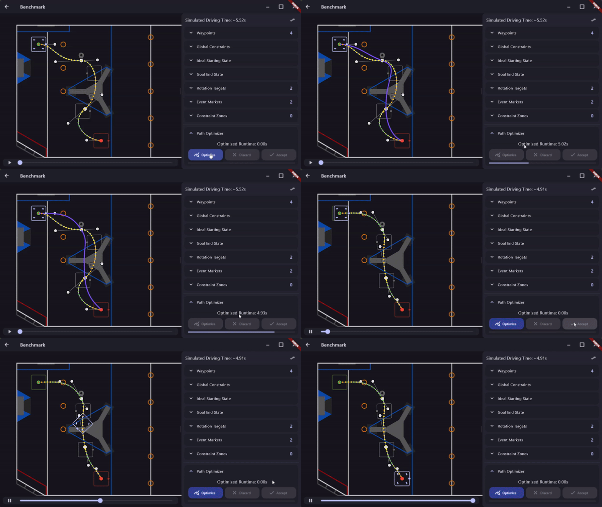
The path editor includes a path optimizer tool that uses a genetic algorithm to adjust the shape of the path, minimizing the total runtime of the path. The optimizer is not guaranteed to find the true "optimal" path shape, but it can be run multiple times if better results are desired.
Path Optimizer Tree

- Optimized Runtime
The total runtime of the current best result of the path optimizer
- Optimize Button
Run the optimizer for the current path. The progress of the optimizer will be displayed in the progress bar below the buttons
- Discard Button
Discard the result of the optimizer
- Accept Button
Accept the result of the optimizer and update the current path to match
Reversed
This reversal checkbox is only available if holonomic mode is off. If selected, the robot will drive backwards when following this path.
Autos
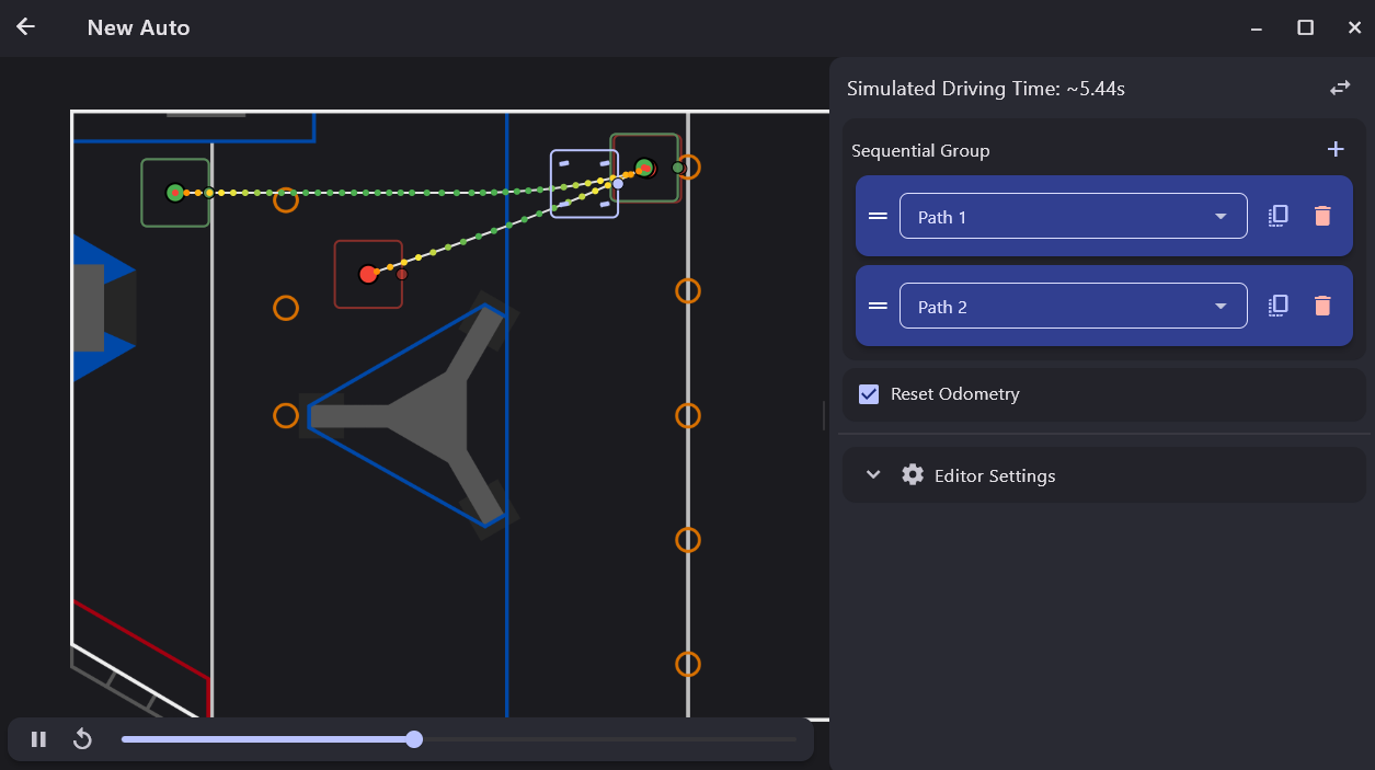
In PathPlanner, autos are used to define a complete autonomous routine. These can then be loaded as a full autonomous command in robot code via PathPlannerLib's auto builder functionality. Each autonomous routine is defined as a sequential command group populated with path following commands, named commands (same as the ones used in path event markers), wait commands, or nested command groups. Path following commands allow you to select any path in the project, this functions as a modular system allowing you to reuse the same path across multiple auto routines.
If you do not wish to use any auto builder functionality, these auto files can be used in PathPlannerLib to get a path group, or list of paths, which will contain all the paths in the auto. This is similar to previous versions' path group system.
Command Group
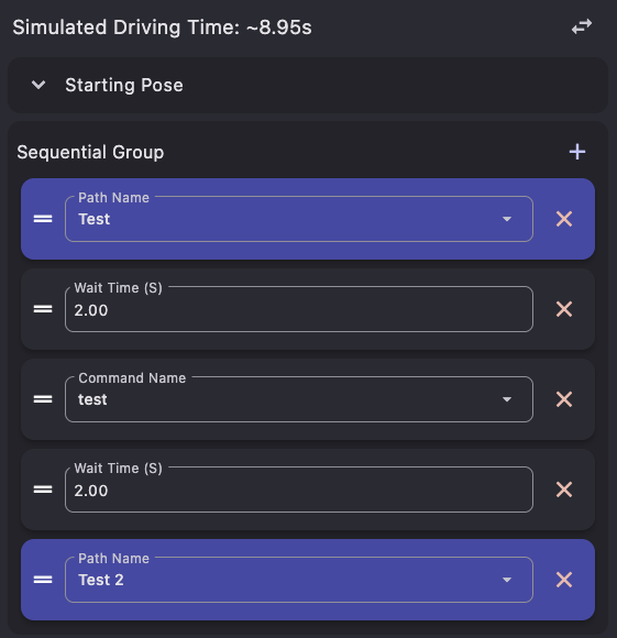
The command group tree is used to define the entire autonomous routine within a sequential command group. This command tree works the same as the command tree for event markers. Commands can be added, removed, or reordered. The same rules that apply to command groups when creating them programmatically still apply here.
Editor Settings
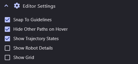
- Snap To Guidelines
When enabled, points will snap to guidelines based on the positions of other points when they are dragged in the editor.
- Hide Other Paths on Hover
When enabled, other paths will be hidden when a path command is hovered in the auto editor.
- Show Trajectory States
When enabled, individual trajectory states will be drawn on top of the path to visualize the spacing between states, as well as the robot velocity at each state. The robot velocity is indicated by the color of the state, which will transition between red and green, which represent 0 m/s and the maximum speed along the path.
- Show Robot Details
Display the position and rotation of the path following preview robot in the editor.
- Show Grid
Display a 0.5 X 0.5 meter grid in the editor